FortiGate-100F - Fan Replacement
Replacing the FortiGate-100F stock fans with Noctua NF-A4x20 PWM fans, with installation photos and before-and-after temperatures.
Summary
Replacing the two stock fans with Noctua NF-A4x20 PWM fans made this home-lab FortiGate-100F noticeably quieter. The trade-off was higher component temperatures: the largest increase was 8.9°C, measured after around four hours of normal use at 22°C ambient.
The stock fans were audible from the bedroom while the firewall was in the garage. The replacement made it quiet enough for this home-lab setup.
Fan Details
Stock Fans
This unit shipped with two Delta FFB0412VHN-F00 fans. The ratings below are from Delta’s specification, sample revision 04, issued 30 January 2020.
- Make: Delta Fan
- Model: FFB0412VHN-F00
- Size: 40x40x28mm
- Airflow at zero static pressure: 15.79 CFM (0.447 m³/min; approximately 26.8 m³/h)
- Static pressure at zero airflow: 0.509 in H₂O (12.94 mm H₂O)
- Noise rating: 45.0 dB(A) average; 49.0 dB(A) maximum
- Input power: 1.92 W nominal; 2.88 W maximum
- Reference speed: 9500 RPM
- Input current: 0.16 A nominal; 0.24 A maximum
- Voltage: 12 VDC rated; 4.5–13.2 VDC operating range
- Product Reference: Here
- Product Datasheet: Stock Fan Datasheet
- Product Image:
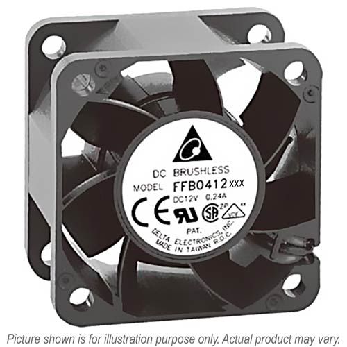
Replacement Fans
Two Noctua NF-A4x20 PWM fans were fitted. The following values are the manufacturer's ratings without the low-noise adaptor:
- Make: Noctua
- Model: NF-A4x20 PWM
- Size: 40x40x20 mm
- Maximum airflow: 9.4 m³/h (5.53 CFM)
- Static Pressure: 2.26 mm H₂O
- Noise Rating: 14.9 dB(A)
- Input power: 0.46 W typical; 0.6 W maximum
- Maximum RPM: 5000 RPM
- Input current: 0.04 A typical; 0.05 A maximum
- Voltage: 12 V rated; 8 V starting voltage; 13.2 V maximum operating voltage
- Product Reference: Here
- Product Image:
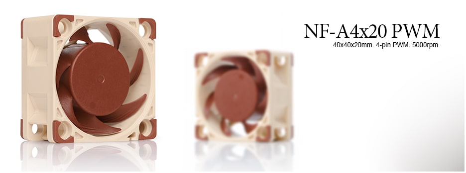
The Noctua fan is 8 mm thinner, with about 35% of the Delta’s rated free-air flow and 17% of its maximum static pressure. The quieter fans move less air and have less pressure available to overcome chassis restrictions.
Process
The stock Delta fans have three leads: black for ground, red for +12 V and blue for tachometer feedback. The Noctua NF-A4x20 PWM has a four-pin connector. Match the header pinout to the fan wiring before connecting it.
Opening this unit required breaking the tamper seal over a chassis screw.
- Disconnect both power inputs, then remove the chassis screws.
- Remove the top panel, exposing the inside of the firewall.
Exposed power-supply components can retain hazardous energy after disconnection. Keep clear of them while working on the fans.
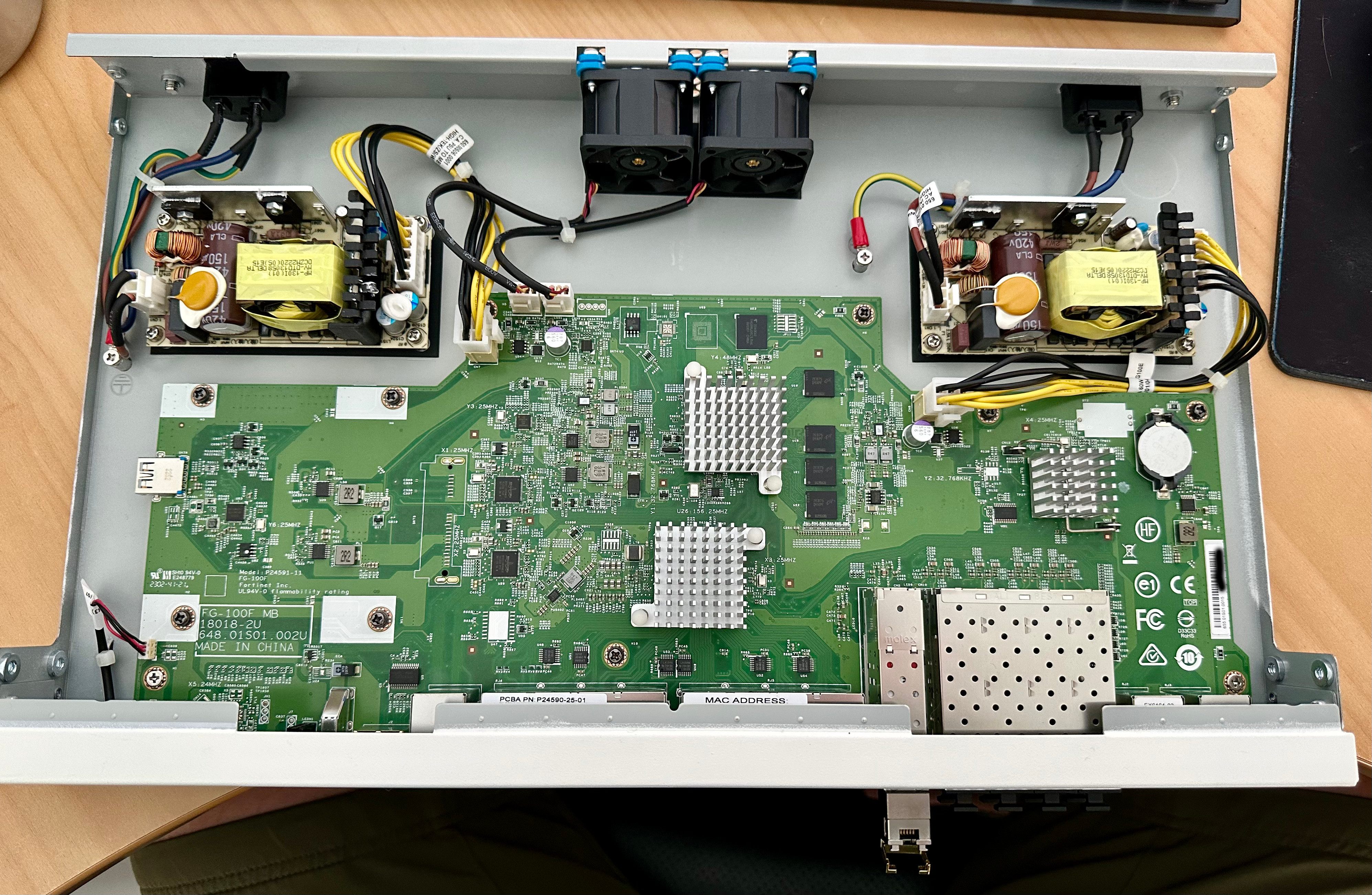
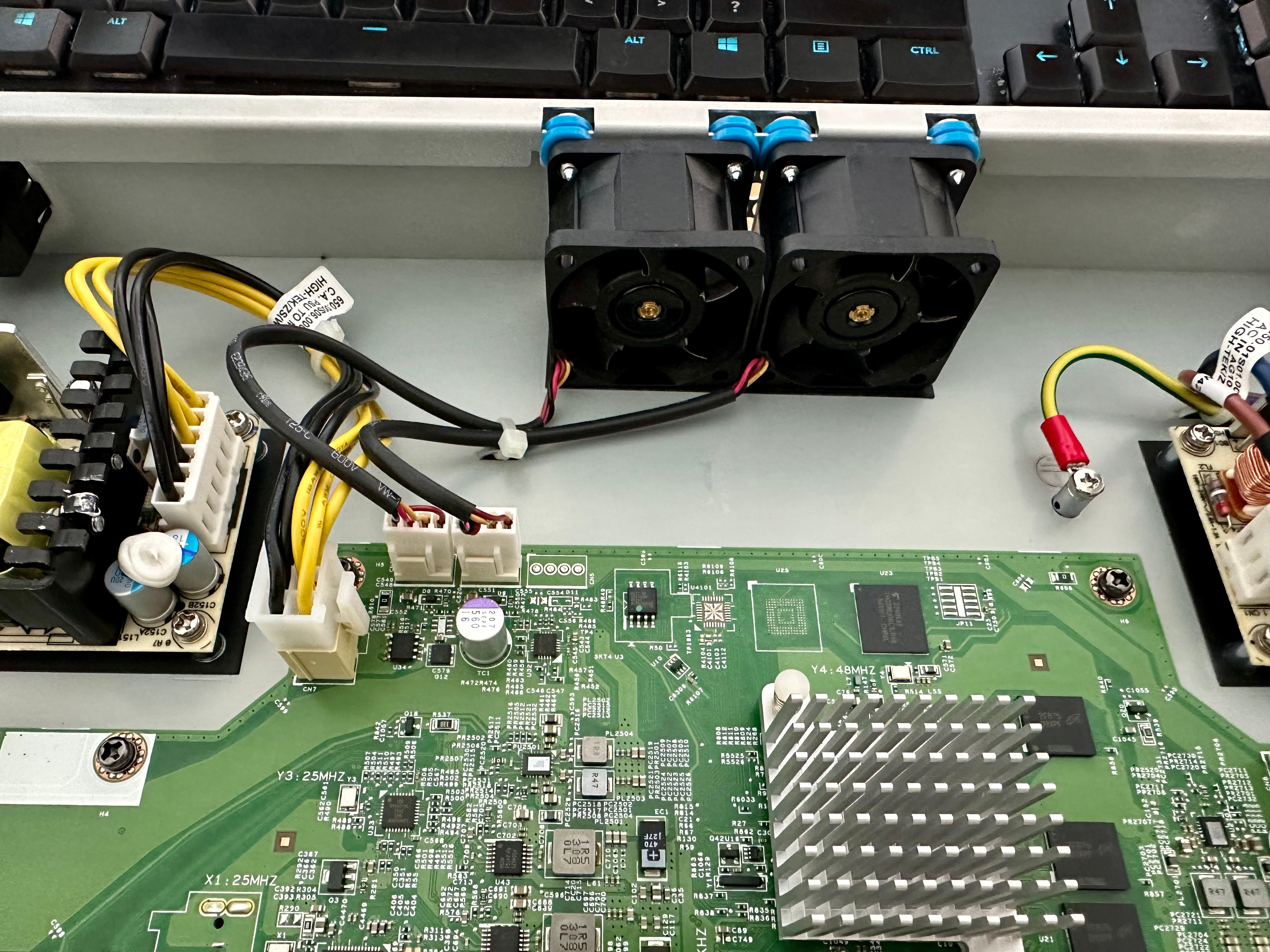 3. Cut the zip tie, unplug the fans and slide upward to remove.
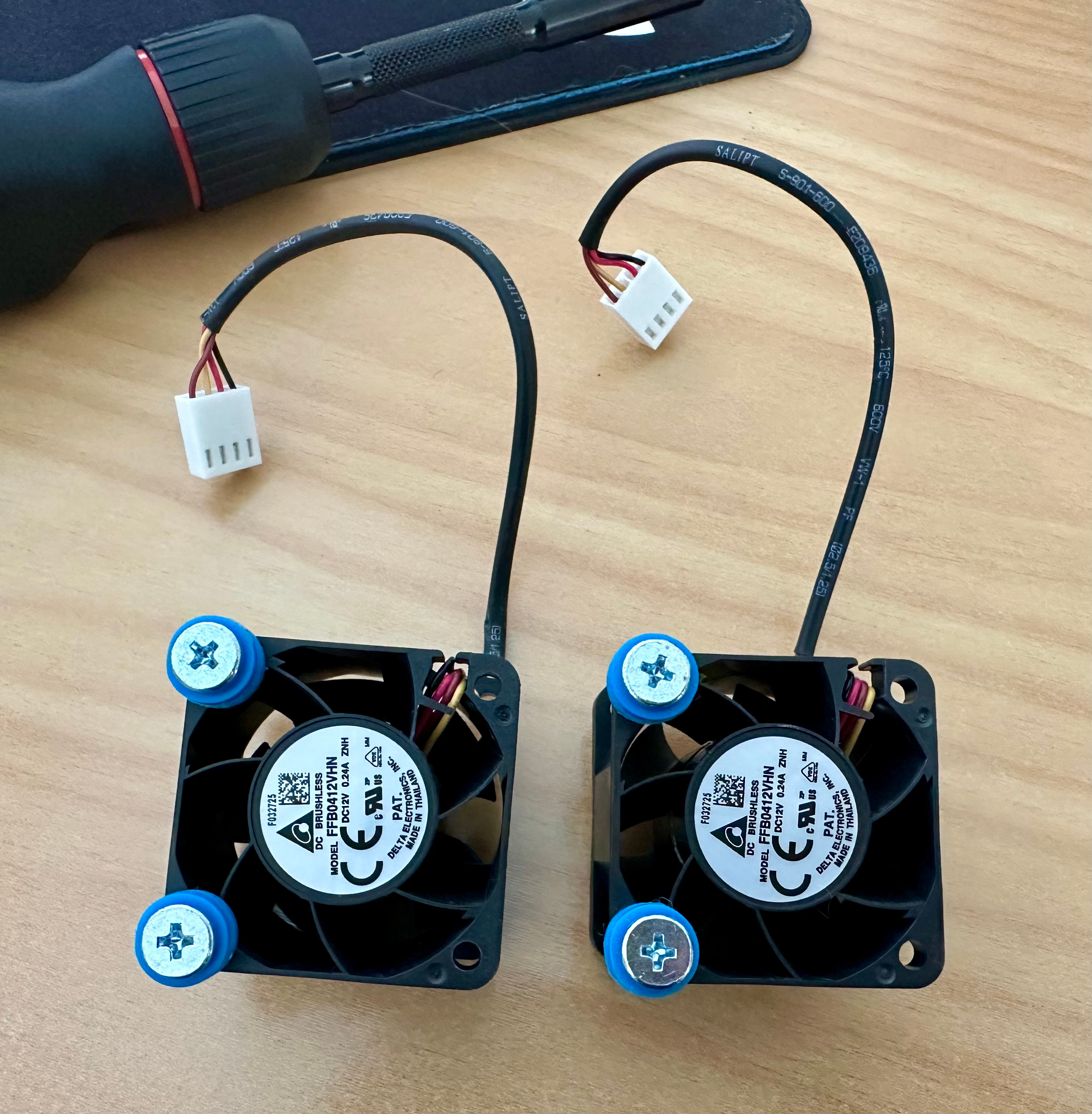 4. Remove the stock fan screws and rubber mounting grommets.
5. Place the rubber grommets on the supplied Noctua screws and lightly tighten.
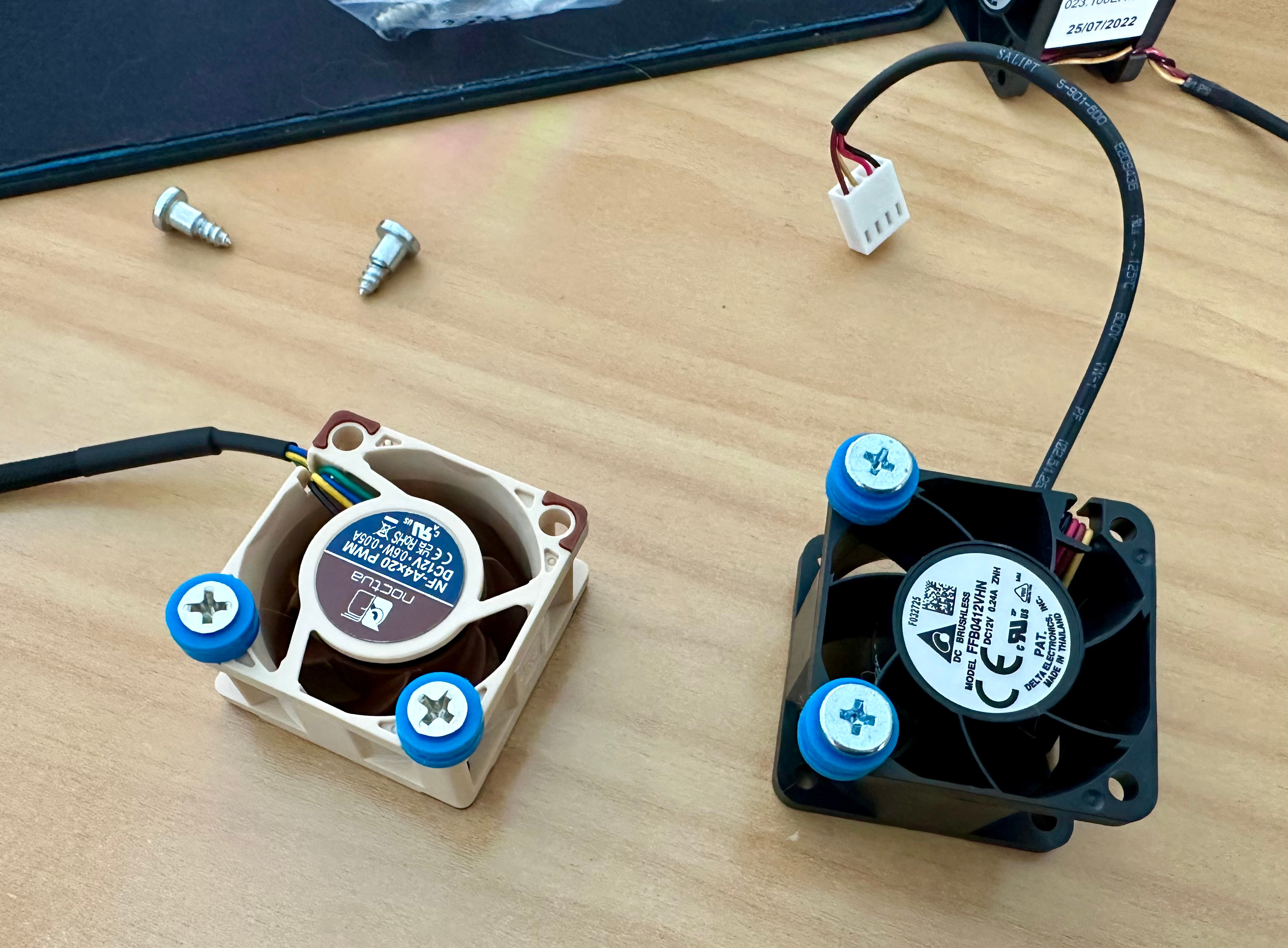 6. Refit the fans in the original airflow direction, checking the moulded airflow arrows, and secure the cables clear of the blades.
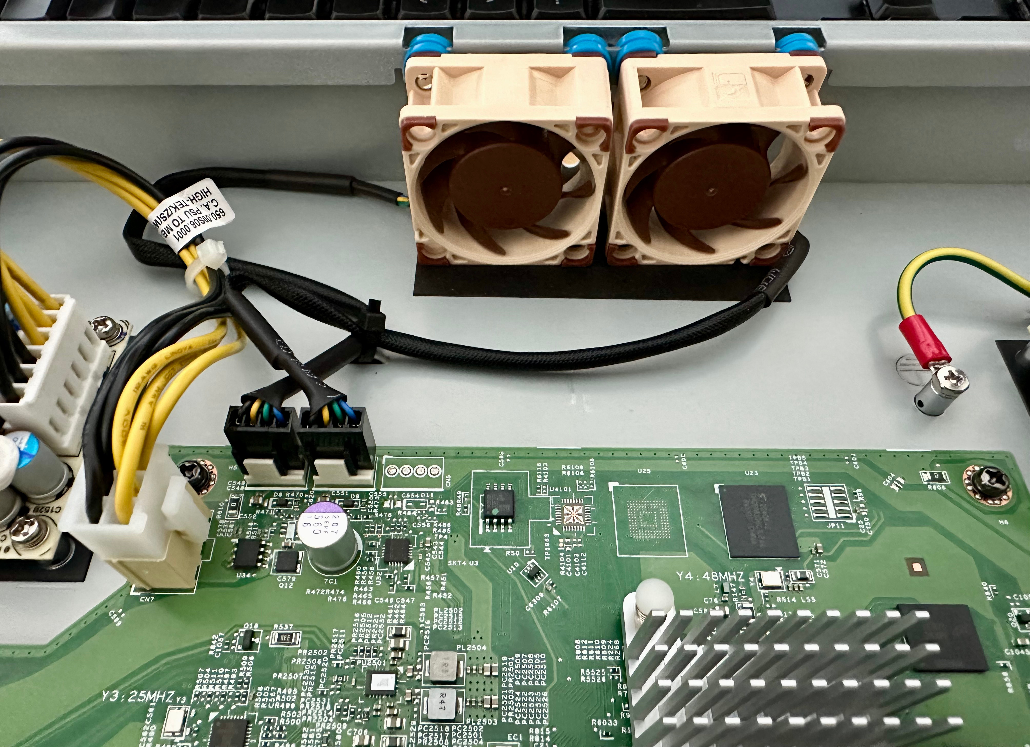
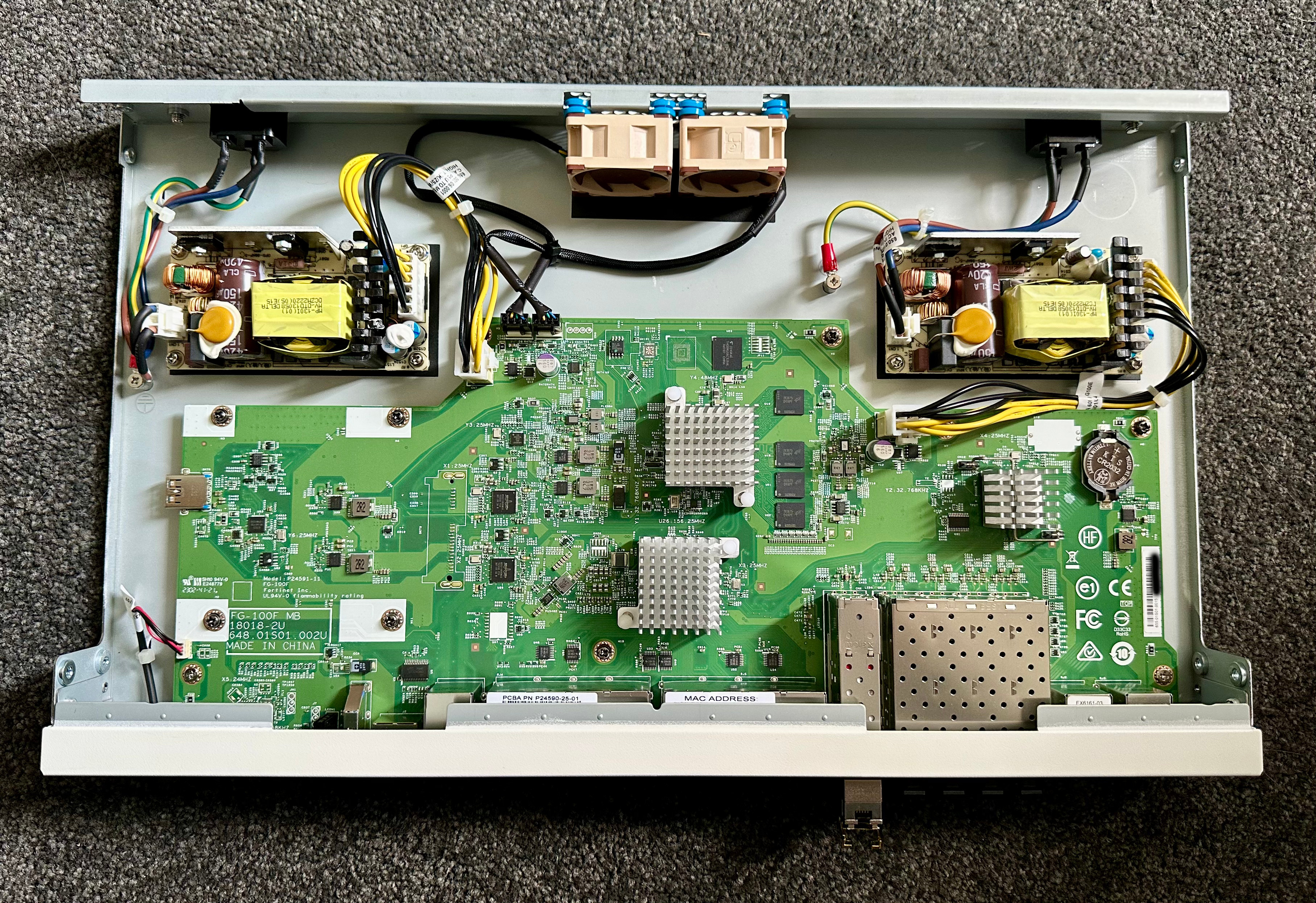 7. Replace the top cover before reconnecting power. Check that both fans start and that sensor readings are plausible.
Results
The readings below were taken after around four hours of normal home-lab use at approximately 22°C ambient, in a room without air conditioning or additional airflow.
Before Replacement
fwl-01 # exec sensor list[HW monitor sensors] 1 PSU [1] ....................... OK 2 PSU [2] ....................... OK 3 SYS Fan1 Speed ................ 7803 RPM 4 SYS Fan2 Speed ................ 7895 RPM 5 TMP1 External Temperature ..... 49.1 C 6 TMP4 ON-DIE Temperature ....... 39.0 C 7 CPU ON-DIE Temperature ........ 49.6 C 8 BCM Switch Temperature ........ 64.6 C 9 B50185 Temperature ............ 66.5 C 10 B50210_1 Temperature .......... 46.3 C 11 B50210_2 Temperature .......... 46.3 CAfter Replacement
fwl-01 # execute sensor list[HW monitor sensors] 1 PSU [1] ....................... OK 2 PSU [2] ....................... OK 3 SYS Fan1 Speed ................ 4341 RPM 4 SYS Fan2 Speed ................ 4369 RPM 5 TMP1 External Temperature ..... 55.2 C 6 TMP4 ON-DIE Temperature ....... 44.0 C 7 CPU ON-DIE Temperature ........ 55.9 C 8 BCM Switch Temperature ........ 73.5 C 9 B50185 Temperature ............ 66.5 C 10 B50210_1 Temperature .......... 49.6 C 11 B50210_2 Temperature .......... 51.3 CComparison
| Sensor | Stock | Noctua | Change |
|---|---|---|---|
| SYS Fan1 Speed (RPM) | 7803 | 4341 | -3462 |
| SYS Fan2 Speed (RPM) | 7895 | 4369 | -3526 |
| TMP1 External (°C) | 49.1 | 55.2 | +6.1 |
| TMP4 ON-DIE (°C) | 39.0 | 44.0 | +5.0 |
| CPU ON-DIE (°C) | 49.6 | 55.9 | +6.3 |
| BCM Switch (°C) | 64.6 | 73.5 | +8.9 |
| B50185 (°C) | 66.5 | 66.5 | 0.0 |
| B50210_1 (°C) | 46.3 | 49.6 | +3.3 |
| B50210_2 (°C) | 46.3 | 51.3 | +5.0 |
Critical Values
All sensors reported normal status. Temperatures were below the listed upper alarm thresholds; TMP1 did not list a threshold.
fwl-01 # execute sensor detail[HW monitor sensors] 1 PSU [1] ....................... OK Type : PSU status (10/0) Sensor status : Normal Alarm : No Value : 1.00 2 PSU [2] ....................... OK Type : PSU status (10/0) Sensor status : Normal Alarm : No Value : 1.00 3 SYS Fan1 Speed ................ 4397 RPM Type : Fan speed (4/0) Sensor status : Normal Alarm : No Lower critical : 200 Upper critical : 14600 4 SYS Fan2 Speed ................ 4369 RPM Type : Fan speed (4/0) Sensor status : Normal Alarm : No Lower critical : 200 Upper critical : 14600 5 TMP1 External Temperature ..... 55.2 C Type : Temperature (1/0) Sensor status : Normal 6 TMP4 ON-DIE Temperature ....... 43.0 C Type : Temperature (1/0) Sensor status : Normal Alarm : No Upper non-critical : 98.9 Upper critical : 113.0 7 CPU ON-DIE Temperature ........ 56.2 C Type : Temperature (1/0) Sensor status : Normal Alarm : No Upper non-critical : 96.2 Upper critical : 110.0 8 BCM Switch Temperature ........ 72.9 C Type : Temperature (1/0) Sensor status : Normal Alarm : No Upper non-critical : 87.5 Upper critical : 100.0 9 B50185 Temperature ............ 66.5 C Type : Temperature (1/0) Sensor status : Normal Alarm : No Upper non-critical : 87.5 Upper critical : 100.0 10 B50210_1 Temperature .......... 49.1 C Type : Temperature (1/0) Sensor status : Normal Alarm : No Upper non-critical : 87.5 Upper critical : 100.0 11 B50210_2 Temperature .......... 50.2 C Type : Temperature (1/0) Sensor status : Normal Alarm : No Upper non-critical : 87.5 Upper critical : 100.0Monitoring and Alerting
- Poll the temperature sensors supported by the model and firmware via SNMP.
- Temperature and fan-failure alerts are available as SNMP traps.
- Automation stitches can be created to alert on the following log message.
Send a test notification to check that alerts reach their destination.